YD Series
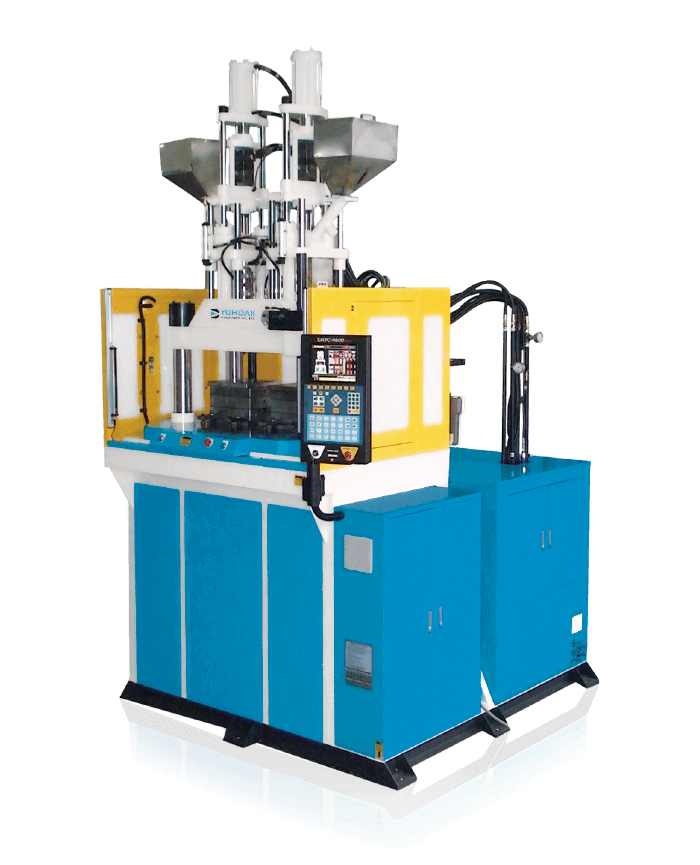
4 Columns Vertical Clamping 2 Color Injection Multi-shot Molding Machine
Product Feature
A. Standard double color vertical injection molding machine:
Designed for multi-shot molding and 4-columns direct-pressure clamping. In the upper mold plate, two separate vertical injection units is installed(separate injection hydraulic oil route) with the addition of round disc for this double injection machine.
- Clamping force is 90- 500TON. Computerized and exclusively configured hydraulic system is used, which is more suitable for the production of general products( or special double-material) injection molding.
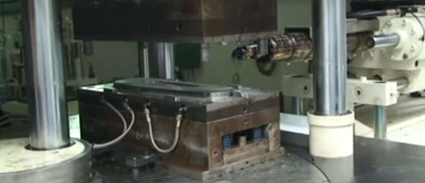
- Two molds are installed on the upper mold plate while three lower molds are installed on the disc. When molding, the disc rotates alternatively at 120°to complete the two-color (two-material) injection molding or overmolding.
- Highly efficient disc with water jacket device in the middle for cooling of the lower mold.
- Expandable computer programs and special multistation disc (i.e. two upper molds and four lower molds). In the two lower modes, automated embedding and removing devices can be installed optionally to achieve automation of the whole machine work and increase production efficiency.
B. Other double color vertical injection molding machine:
- Type 1: A set of independent vertical “injection units” is added onto the upper mold plate of the original injection machine to form a double injection machine.
- Example: YH / YR / YC models + vertical injection.
- Type 2: On the original injection machine, one or more sets of independent horizontal (level) injection units is combined to form a double injection machine.
- Example: YH / YR models + horizontal injection
- Type 3: The two-colors injection molding machine is combined to form a double injection machine by sharing a common disc.
-
Example: a. YH model + YT model + disc (2 ~ 4 stations)
b. YH model + YH model + disc (2 ~ 4 stations)

Hardware & Household Items

Plug Series Items

Double Injection Molding Items

Consumer Electronics Items
Main specifications
Swipe the table to see more informations
|
|
|
|
|
|
|
|
|
|
|||||||||||||||||||||||||||||||||||||||||||||||||||||||||||||||||||||||||||||||||||||||||||||||||||||||||||||||||||||||||||||||||||||||||||||||||||||||||||||||||||||||||||||||||||||||||||||||||||||||||||||||||
|---|---|---|---|---|---|---|---|---|---|---|---|---|---|---|---|---|---|---|---|---|---|---|---|---|---|---|---|---|---|---|---|---|---|---|---|---|---|---|---|---|---|---|---|---|---|---|---|---|---|---|---|---|---|---|---|---|---|---|---|---|---|---|---|---|---|---|---|---|---|---|---|---|---|---|---|---|---|---|---|---|---|---|---|---|---|---|---|---|---|---|---|---|---|---|---|---|---|---|---|---|---|---|---|---|---|---|---|---|---|---|---|---|---|---|---|---|---|---|---|---|---|---|---|---|---|---|---|---|---|---|---|---|---|---|---|---|---|---|---|---|---|---|---|---|---|---|---|---|---|---|---|---|---|---|---|---|---|---|---|---|---|---|---|---|---|---|---|---|---|---|---|---|---|---|---|---|---|---|---|---|---|---|---|---|---|---|---|---|---|---|---|---|---|---|---|---|---|---|---|---|---|---|---|---|---|---|---|---|---|---|---|---|---|---|---|---|---|---|
*Specifications are subject to change without notice.
*Screw and clamping force are optional.